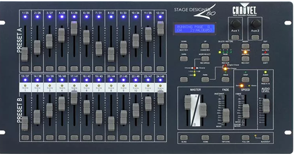
Chauvet Stage Designer 50
|
 |
| ARCHITECTURE |
|---|
| The Chauvet Stage Designer 50 (SD50) desk is a fairly versatile unit that can be thought of as three unique lighting controllers in one package. It can be configured for 12 or 24 channel two scene preset, 24 or 48 channel single scene with master, or 48 channel memory board operation. All modes have adjustable fade in, fade out time. In the memory board configuration, it can store and playback up to a combination of 48 scenes or chases and each chase can have as many as one thousand unique steps. Regardless of which mode the desk is configured, any of it's 48 DMX channels can be assigned to any fader, in any combination, with up to 48 channels on one fader in "channel" mode. In the context of the SD50, a scene is a chase consisting of only one step. Memory playback can be executed manually, one step at a time, or by an adjustable timing ranging from a second to ten minutes, or by audio trigger. Chase speed can be stored into any chase (called beat) or controlled by the speed slider or syched to audio. Chases can be reversed and channels can be temporarily removed from a chase. Chases can be single or mixed. |
|
Modes: The eleven main modes and three submodes include:
|
| Electrically, the SD50 provides both a standard 3 pin XLR and 5 pin XLR DMX wired in parallel and the desk can be inserted anywhere in the DMX universe—that is, you can feed the 3 pin to one group of fixtures and the five pin to another group, if desired. If the DMX line is long, it should be terminated at both ends. The phase reversal switch is not needed and should always be set in the normal phase as reverse phase DMX fixtures have been obsolete for a very long time. A DMX universe is limited to a maximum of 32 physical devices regardless of how many of the 512 DMX channels are assigned. |
| There are two assignable controls marked Aux 1 and Aux 2. These can be used for remote control of certan DMX effects such as strobe lights or hazers if the device is properly equipped to do so. These controls can be configured in one of three modes and the DMX channel assigned to them is 'disconnected' from other desk operations. They operate independently from each other and from the various scenes, channels, and other features. |
| MIDI: The Stage Designer is an excellent MIDI to DMX converter capable of accepting 80 notes from MIDI channels 1 through 16. It will render DMX output based on either 48 programmed scenes or 24 channels. (See table below). However, the real reason for MIDI on the SD5O is slaving mulitple SD50s will allows expansion of additional channels in 48 channel increments allowing access to hundreds of DMX channels. These additional channels can be controlled as either the first 48 programmed scenes or the first 24 faders. Note that each SD-50 will have it's own programming and channel assignments. Finally, MIDI can be used to copy the programing of one SD50 to another. |
|
Caveates: The desk is primarily intended for use controlling dimmers and generic LED fixtures (PARs, LightBars, etc) running in basic DMX mode and in this way, it works very well within its capabilities. Intellgent fixtures are better controlled with an Obey 10 or 40 and moving lights (yokes and scanners) with an Obey70 which are 'fixture' oriented. Faders 25-48 (Page B) are mostly useful in creating "looks" in the memory mode where they can be incorporated into either a scene or into steps in a chase. They are difficult to use in the two scene preset mode. In the single scene mode, you can use either Page A (1-24) or Page B (25-48) separately, but never together. So, for example, it would be possible to use Page B for house lights and curtain warmers, then switch to Page B for the production. In the event, you try to use them together, expect unpredictable behavior when switching back and forth between the two pages. Channels 25-48 can be usefully patched to channels 1-24. By default, all of the SD50s DMX channels (1-48) are assigned to faders 1 to 48 and can be easily reset to that configuration. Since all 48 channels can be patched to any fader, it's very possible that at any given time, any or all channel(s) may NOT be assigned to it's default assignment and may lead to unexpected fixture behavior. Either reset to default or confirm channel patches are correct prior to use. Be aware that not every control is useful or functional in every mode. Moreover, the same control may serve different purposes depending on the selected mode. Some controls are labeled with several mode dependent functions, others are not. The desk indicators are sufficiently bright for use in bright spaces or outdoors, however, in a darkened room may be overly bright. If this is the case, the only practical remedy is to tape them. Note that the [PARK] button toggles between single and multi chase mode. Scenes need to be multi mode to work properly. When using MIDI to connect consoles, be aware that scenes and channels operate concurrently so when a channel is triggered on the controlling console, the controlled console will also respond which can result in unexpected behavior. DMX works a little differently from traditional analog control. With analog controllers, dimmers output power to the attached fixture(s) proportionally with the provided control voltage. Commonly, at zero volts, the fixture is full off, and at ten volts, it is at full brightness. If the control signal is lost, the fixtures all go black. With DMX, each fixture stays at whatever level it last received when the signal is lost until it gets a new control command. When "blackout" is activated, every channels gets a "0" level sent. When 'Full On' is activated, every channel gets a "255" level sent. If a fixture appears "stuck", this doesn't necessarily indicate a problem with the desk, it mostly means the fixture has stopped receiving DMX commands. Try nudging the associated fader slighly to send it a fresh command. |
|
Power Supply: 12 Volts DC, 500 milliAmperes, 5.5 X 2.1 mm plug |
| The Stage Designer 50 desk features a great deal of functionality condensed into a modest number of multifunction controls which do differnt things depending on the current mode. These control functions can be divided into groups by function: Mode Selection, Configuration, and Execution. Generally speaking, mode controls maintain their current status until explicitly changed. Execution controls work while in "RUNNING" mode, and Configuration controls operate within specific mode context. |
MODE SELECTION
| MIDI IN MODE | |
|---|---|
|
To Enter: Hold [SHIFT] then tap [1][1][1] LCD Display shows "MIDI IN" Tap [1] through [16] as desired to select |
To Exit: Hold [SHIFT] then tap [REC EXIT] LCD Display shows "RUNNING" |
|
Specifies which MIDI channel (1-16) to respond to. Allows this Stage Designer 50 to receive commands
from another SD50 which allows controlling the SD50 from a remote MIDI controller or another SD50. See
MIDI table for specific commands the console will respond to. |
|
| MIDI OUT MODE | |
|---|---|
|
To Enter: Hold [SHIFT] then tap [2][2][2] LCD Display shows "MIDI OUT" Tap [1] though [16] as desired to select |
To Exit: Hold [SHIFT] then tap [REC EXIT] LCD Display shows "RUNNING" |
|
Specify which MIDI channel (1-16) to output to. Used to slave additional Stage Designer 50s to this one.
See MIDI table for what MIDI codes will be sent.
|
|
| MIDI FILE DUMP RECEIVING MODE | |
|---|---|
|
To Enter: Hold [SHIFT] then tap [3][3][3] LCD Display shows "MIDI FILEDUMP RECVING" |
To Exit: Hold [SHIFT] then tap [REC EXIT] LCD Display shows "RUNNING" |
|
Receives a memory dump from another Stage Designer 50. |
|
| MIDI FILE DUMP SENDING MODE | |
|---|---|
|
To Enter: Hold [SHIFT] then tap [4][4][4] LCD Display shows "MIDI FILEDUMP SENDING" |
To Exit: Hold [SHIFT] then tap [REC EXIT] LCD Display shows "RUNNING" |
| Sends a memory dump to another Stage Designer 50. | |
| SET SPEED RANGE TO 5 MINUTES | |
|---|---|
|
To Execute: Hold [SHIFT] then tap [5][5][5] The amber '5MIN' indicator glows. |
|
| This sets the range of the speed slider from 1 Second to 5 minutes. | |
| SET SPEED RANGE TO 10 MINUTES | |
|---|---|
|
To Execute: Hold [SHIFT] then tap [10][10][10] The amber '10MIN' indicator glows. |
|
| This sets the range of the speed slider from 2 Seconds to 10 minutes. | |
| CHANNEL MODE | |
|---|---|
|
To Enter: Hold [SHIFT] then tap [6][6][6] LCD Display shows "CHANNEL" |
To Exit: Hold [SHIFT] then tap [REC EXIT] LCD Display shows "RUNNING" |
| Allows reassignment of any of 48 DMX output channels to any control fader. A control fader can accept any number of output channels. Stacking output channels on faders can result in unassigned faders. | |
| AUX 01 MODE | |
|---|---|
|
To Enter: Hold [SHIFT] then tap [7][7][7] LCD Display shows "AUX 01" |
To Exit: Hold [SHIFT] then tap [REC EXIT] LCD Display shows "RUNNING" |
| Allows configuration of control mode and channel assignment for auxillary one. Default values are mode 1, channel 1 after system reset. | |
| AUX 02 MODE | |
|---|---|
|
To Enter: Hold [SHIFT] then tap [8][8][8] LCD Display shows "AUX 02" |
To Exit: Hold [SHIFT] then tap [REC EXIT] LCD Display shows "RUNNING" |
| Allows configuration of control mode and channel assignment for auxillary two. Default values are mode 1 and channel 1 after system reset. | |
| RECORD MODE | |
|---|---|
|
To Enter: Hold [SHIFT] then tap [1][5][6][8] Red "Record" indicator lights up LCD Display shows "RECORD" |
To Exit: Hold [SHIFT] then tap [REC EXIT] Red "Record" indicators goes dark LCD Display shows "RUNNING" |
| Allows creation and editing of 48 programs consisting of either scenes or chases of up to 1000 steps. | |
| SYSTEM RESET MODE | |
|---|---|
|
To execute a complete erase of all assignments, settings, and programs: Hold [SHIFT] then tap [1][5][6][8] to enter record mode LCD Display is showing"RECORD" Hold [SHIFT] then tap [1][3][2][3] The SD50 is now reset to factory default settings. |
To Remain in RECORD MODE: Do nothing. LCD Display shows "RECORD" |
To Exit back to RUNNING MODE: Hold [SHIFT] then tap [REC EXIT] LCD Display shows "RUNNING" |
| RUNNING MODE | |
|---|---|
|
To Enter: Hold [SHIFT] then tap [REC EXIT] Red "Record" indicator goes dark LCD Display shows "RUNNING" |
To Exit: Enter Channel, Aux1, Aux2, Record or other modes. Red "Record" indicator lights up. LCD Display shows "CHANNEL", "AUX1", "AUX2", or "RECORD". |
| RUNNING SUBMODES | |
|---|---|
|
Allows manual operation as two scene preset desk, one scene desk, or playback of scenes/chases. You can switch modes at anytime, however be aware that outputs are sticky and will remain however they were set. To clear a running cue, you may have to return to the mode that enabled it. You may also have to switch from Page A to Page B or vice versa. |
Enable Scene/Chase playback Submode: Tap [MODE SELECT] until red indicator glows Red indicator is marked "Scene"" * "Chase" Programs can be documented using our memory controller schedule. |
|
Enable 12 channel Two Scene Preset Submode: Tap [MODE SELECT] until yellow indicator glows Yellow indicator is marked "1-12A"" * "1-12B" Fader assignments can be documented using our two scene controller schedule. |
|
|
Enable 24 channel One Scene Submode: Tap [MODE SELECT] until green indicator glows Green indicator is marked "1-24A" * Fader assignments can be documented using our single scene controller schedule. |
|
| %OR255 BUTTON | |
|---|---|
This control is used to toggle between display ranges of 0-100 (%) or 0-255 (DMX value) on the LCD display.
Whenever any variable control is moved, the bottom half of the display indicates which control is moving
and it's current value. Normally, percentage display is the most useful, however, most fixtures that have
advanced features need exact DMX values. This control can be operated anytime.
Hold [SHIFT] then tap [%OR255] |
CONFIGURATION
|
CHANNEL MODE Viewing Channel Assignments |
|---|
|
Note: In Channel mode, it is not possible to toggle pages between PAGE A and PAGE B. It is necessary
to exit CHANNEL mode, switch to the other page and re-enter channel mode. When in CHANNEL mode, the bump buttons correspond to the DMX output channels. Press any bump button corresponding to the DMX channel of interest. Observe the LCD display. The value following CHNO: is the DMX channel, the value following SLDNO is the fader it's currently assigned to. |
|
CHANNEL MODE Changing Channel Assignments |
|---|
|
Note: See the article about "Viewing Channel Assignments" as that applies here as well. Start by viewing the channel you wish to re-assign. Press and hold the [RECORD] button, then tap the bump button where it is to be assigned. Repeat as needed until all channels are properly assigned. Reassigning a channel from PAGE A to PAGE B or vice versa requires a few extra steps as follows: View the channel to be reassigned Extra steps: Hold [SHIFT] then tap [REC EXIT]Press [RECORD] then tap [bump button where it is to be assigned] This is necessary because PAGE A_B cannot be toggled while in CHANNEL mode. Patches can be documented using our patch schedule. |
|
AUX 01 -or- AUX 02 MODE Configuring Auxiliary Controls |
|---|
|
Setting mode: There are three modes: Mode 1, Mode 2, and Mode 3. Mode one disables the auxiliary control such that it does nothing and is the default value for both controls. Mode two is useful for devices requring a continuously variable control signal such as controlling the pan or tilt on a moving light. The encoder knob features a range from 0 to 255 and the bump button has no function. Using the two auxiliaries together is ideal for controlling the pan and tilt of a remote followspot for example. Mode three is useful for devices that need an off/on control signal when the button is pressed which is suitable for controlling a strobe, hazer or similar device. In mode 3, both the bump button and the encoder knob function and can be used to control a strobe speed, or when set to the maximum 255, will produce the desired off/on capabilty to control a DMX hazer. For mode 1: Press [RECORD], then [1] |
|
Assigning channel: Either auxiliary control can be assigned to any channel from 1 to 48. When the control is set to mode two, the auxiliary control *replaces* the normal fader. When the control is set to mode three, the auxiliary control works as 'highest takes precedence' with the fader. Press [RECORD], then [Bump for the assigned channel] |
|
Running Mode notes: Blackout: both auxiliary controls go to zero. Dark: has no effect on either control. Full On: drives both outputs to 255 and overrides Blackout. Scenes/Chases have no effect on either control CAUTION! Operating the "Full On" button can cause unintended device movements or trigger effect devices connected to the auxiliary controls. |
|
RECORD MODE Clearing the program buffer |
|---|
The program buffer is where programs (scenes and chases) is stored while
being built. You can only clear the program buffer while in RECORD mode.
LCD Display should show "RECORD"The buffer is now erased. |
|
RECORD MODE Recording a Scene Program |
|---|
LCD Display should show "RECORD", if not hold [SHIFT] then tap [1][5][6][8]. Programs can be documented using our scene schedule. |
|
RECORD MODE Recording a Chase Program |
|---|
LCD Display should show "RECORD", if not, hold [SHIFT] then tap [1]][5][6][8]. Programs can be documented using our scene schedule. Steps can be documented using our step schedule. |
|
RECORD MODE Deleting an entire program (scene or chase) |
|---|
LCD Display should show "RECORD", if not, hold [SHIFT] then tap [1][5][6][8]. |
|
EDIT MODE Insert a step or steps into an existing chase program |
|---|
|
LCD Display should show "RECORD", if not, hold [SHIFT] then tap [1][5][6][8]. Hold [SHIFT] then tap [REC CLR] to clear program buffer. Tap [MODE SELECT] until it's at 1-24A. Green indicator glows. Adjust [FADERS - Page A] to set the desired "look" for Page A (faders 1-24). Hold [EDIT] then tap [SCENE 1-12] to enter Edit mode.LCD Display should show "EDITING" Tap [MODE SELECT] until it's at scene/chase Amber indicator glows. Tap [STEP] until at desired insertion point. Tap [INSERT] and program buffer will be inserted. Indicators will flash indicating successful insert. Hold [SHIFT] and tap [REC EXIT] then tap [REC EXIT] again to exit to running mode. |
|
Note: The new step or steps will be inserted *before* the insertion point and following
step numbers will increase according to the number of steps added. |
|
EDIT MODE Deleting a step from a chase program |
|---|
|
LCD Display should show "RECORD", if not, hold [SHIFT] then tap [1][5][6][8]. Hold [EDIT] then tap [SCENE 1-12] to enter Edit mode.LCD Display should show "EDITING" Tap [STEP] until desired step to delete is reached.Display shows current step numberHold [SHIFT] tap [REC EXIT] then tap [REC EXIT] again to return to Running mode. |
|
Note: The step deleted was the program step *on* the deletion point and
the following steps all moved down one increment. |
|
EDIT MODE Modifying a step in a chase program |
|---|
|
LCD Display should show "RECORD", if not, hold [SHIFT] then tap [1][5][6][8]. Hold [EDIT] then tap [SCENE 1-12] to enter Edit mode.LCD Display should show "EDITING" Tap [STEP] until desired step to delete is reached.Display shows current step numberHold [SHIFT] then tap [REC EXIT] then tap [REC EXIT] to return to running mode. Note: Any channel from 1-48 can be modified. Each tap increases/decreses dmx value one unit. You can press and hold bump button to quickly change values. |
EXECUTION
|
RUNNING MODE 12 or 24 Channel, Two Scene Preset Desk |
|
|---|---|
| Control | Function |
| [SHIFT][PAGE A/B] | Toggles between channels 1-12 and 13-24 anytime. |
| PRESET A CH 1-12 or 13-24 INDICATORS | Blue indicator showing the channels which are active. |
| PRESET A CH 1-12 or 13-24 FADER | Sets variable output level (0-255) for the channel. |
| PRESET A CH 1-12 or 13-24 BUMP | Force output to full (255) for the channel. |
| PRESET B CH 1-12 or 13-24 INDICATORS | Blue indicator showing the channel which are active. |
| PRESET B CH 1-12 or 13-24 FADER | Sets variable output level (0-255) for the channel. |
| PRESET B CH 1-12 or 13-24 BUMP | Force output to full (255) for the channel. |
| PRESET A MASTER | Master control for Preset A. When slider is 'up' all preset A faders 1-24 are active. |
| PRESET B MASTER | Master control for Preset B. When slider is 'down' all preset B faders 1-24 are active. |
| FADE SLIDER | Sets the fade in and fade out times for all faders. |
| BLACKOUT | Toggles between output enabled/disabled. When active, all outputs send DMX 0 value. |
| BLACKOUT INDICATOR | Yellow indicator glows when output is enabled. |
| FULL ON | Drives all channels to full on DMX 255 value |
| DARK | Momentarily drives all channels to DMX 0 value. |
| Note: To access the second bank (channels 13-24), toggle back and forth between the two banks with the [SHIFT][PAGE A/B]. All channels are affected by the submasters. | |
|
RUNNING MODE 24 or 48 Channel, One Scene Desk |
|
|---|---|
| [SHIFT][PAGE A/B] | Toggles between channels 1-24 and 25-48 anytime. |
| CH 1-24 or 25-48 INDICATORS | Blue indicator showing the channels which are active. |
| CH 1-24 or 25-48 FADER | Sets variable output level (0-255) for the channel. |
| CH 1-24 or 25-48 BUMP | Force output to full (255) for the channel. |
| MASTER A | Master control for faders 1-12 (Page A) or 25-36 (Page B). When slider is 'up' all faders are active. |
| MASTER B | Master control for faders 13-24 (Page A) or 37-48 (Page B). When slider is 'down' all faders are active. |
| FADE SLIDER | Sets the fade in and fade out times for all faders. |
| BLACKOUT | Toggles between output enabled/disabled. When active, all outputs send DMX 0 value. |
| BLACKOUT INDICATOR | Yellow indicator glows when output is enabled. |
| FULL ON | Drives all channels to full on DMX 255 value |
| DARK | Momentarily drives all channels to DMX 0 value. |
| Note: To access the second bank (channels 25-48), toggle back and forth between the two banks with by holding [SHIFT] and pressing [PAGE A/B]. All channels are affected by the masters. | |
|
RUNNING MODE Memory Desk |
|
|---|---|
| When in Memory Desk mode, the 48 stored programs can be executed. To execute a program, select the appropriate memory page and trigger it by either adjusting the scene fader or pressing the scene bump. Additionally, while in this mode, some channels can be manually operated. | |
| [SHIFT] [PAGE A/B] | Toggles between fader page A (channels 1-12) and page B (channels 25-36) any time. See Note 2. |
| MANUAL MASTER | Master control for all manual channels. When slider is 'up' upper bank faders 1-12 or 25-36 are active. See Note 2. |
| CH 1-12 or 25-36 INDICATORS | Blue indicators showing the channel is active. See Note 2. |
| CH 1-12 or 25-36 FADER | Sets variable output level (0-255) for the channel. See Note 2. |
| CH 1-12 or 25-26 BUMP | Force output to full (255) for the channel. See Note 2. |
| CH 13-24 or 37-48 INDICATORS | Blue indicators showing the channel is active. See Note 2. |
| PAGE | Switches between pages 1,2,3, and 4. See note 1. |
| SCENE MASTER | Master control for all programs. When slider is 'down' all programs are active. See Note 1. |
| SCENE 1-12 INDICATORS | Amber indicator showing the scenes or chases which are active. See Note 2. |
| SCENE 1-12 FADER | Sets variable output level (0-255) for the program. See Note 2. |
| SCENE 1-12 BUMP | Force program output to full (255) for the program. See Note 2. |
| FADE SLIDER | Sets the fade in and fade out times for all faders and programs (scenes or chases). This control operates independently of other controls. |
| BLACKOUT | Toggles between output enabled/disabled. When active, all outputs send DMX 0 value. |
| BLACKOUT INDICATOR | Yellow indicator glows when output is enabled. | FULL ON | Drives all channels to full on DMX 255 value |
| DARK | Momentarily drives all channels to DMX 0 value. |
| AUDIO INDICATOR | Indicates whether free running chases are controlled by audio when on. |
| AUDIO BUTTON | Toggle between audio and speed slider control of free running chases. Does not affect beat chases. |
| AUDIO SLIDER | Sets the audio sensitity for all free running chases. |
| SPEED SLIDER | Sets the chase speed for all free running chases. |
| STEP | When speed control is set to 'show mode', bumps the chase to the next step. |
| HOLD | Freezes all chases whether beat or freerunning. |
| BEAT REV | Reverses direction of beat chase execution. |
| CHASE REV | Reverses direction of freerunning chase execution. |
| REV ONE | Reverses direction of a single chase. Hold [REV ONE] then tap the desired scene bump. |
| ALL REV | Reverses direction of both beat and freerunning chases. |
| BLIND | Removes a channel from a chase. Hold [BLIND] then tap the channel bump. A channel in blind mode can be operated manually. |
| HOME | Cancels a channel in blind. Hold [HOME] then tap the channel bump. The channel will return to programmed scene or chase operation. |
| PARK | Toggles between single chase and mix chase mode. In single chase mode, one chase executes, then the next, and so on. In mix chase, all active chases execute at the same time. If the program is a scene, only only one scene is active at a time in single chase mode. In mix mode, scenes can be blended. |
| KILL INDICATOR | Amber indicator glows when kill mode is active. |
| ADD KILL | This control affects how Scene Bump buttons 1-12 affect the behavior of Programs 1-12 and toggles between "add" mode and "kill" mode. In "Kill" mode, operating any one or more of the bumps causes all of the other programs to go dark. In "Add" mode, operating any one or more of the bumps allows all of the other programs to execute normally. This is also called pile on. Hold [SHIFT], then tap [ADD KILL] |
| Note 1:
The SD50 program memory is divided into four pages and
each page stores twelve programs. You can switch pages at any time.
Any program running will continue until a new program is selected
in the different page. When a program has only one step, it behaves as a scene. When it has more than one, it behaves as a chase. |
|
| Note 2: When console is set to Page A, the upper bank of blue indicators, faders, and bumps and the associated master fader control channels 1 through 12. The lower bank of blue indicators indicate the status of channels 13 through 24. When console is set to Page B, the upper bank of blue indicators, faders, and bumps and the associated master fader control channels 25 through 36. The lower bank of blue indicators indicate the status of channels 37 through 48. Whether the console is set to Page A or B, the lower bank of amber indicators, faders and bumps are associated with the programs selected by the page button and display lights. See Note 1. | |
|
RUNNING MODE Setting or Clearing a Beat on a Chase |
|---|
| When a chase has a preset speed value its said to be a "beat" chase and its execution is not affected by either the speed or audio slider. When a chase is set to 'Show Mode' it is said to be a 'freerunning' chase and is affected by either the speed or audio slider. Beat chases can be reversed separately from freerunning chases or they can be reversed together. Either beat or freerunning chases can be reversed independently. |
To set beat on a chase:Enter "Running" mode. |
To clear a beat from a chase to return it to free running:Enter "Running" mode. |
MIDI TO DMX
| ABOUT MIDI |
|---|
| Musical Instrument Digital Interface (MIDI) was originally created in the 1980s to link
electronic musical instruments. Chauvet adapted MIDI for lighting control and it's a
feature in their controllers. MIDI consists of sixteen "channels" using hexadecimal coding
0 through F, however, Chauvet maps those to decimal 1 through 16 consistent with how it's
commonly deployed in musical instruments. There are two modes provided to allow the user
to select both MIDI in and MIDI output channels which allows consoles to be networked on
a MIDI network. It's possible for a PC running MIDI to communicate on all 16 channels,
though SD50s are better thought of as terminal nodes. Next, each MIDI channel has 128 possible "Notes" numbered from 0 through 127. The SD50 uses 80 notes, numbered from 22 through 102 where 'Middle C' is at Note 60. Each channel can emit or respond to a 'Note On' or 'Note Off' command. The following table maps out the respective command actions to their associated MIDI notes. |
|
MIDI MAPPING 80 Notes | |||
|---|---|---|---|
| Octave | Note | MIDI Note | SD50 Command Action |
| 0 | B | 22 | Page 1, scene 1 is active. |
| B# | 23 | Page 1, scene 2 is active. | |
| 1 | C | 24 | Page 1, scene 3 is active. |
| C# | 25 | Page 1, scene 4 is active. | |
| D | 26 | Page 1, scene 5 is active. | |
| D# | 27 | Page 1, scene 6 is active. | |
| E | 28 | Page 1, scene 7 is active. | |
| F | 29 | Page 1, scene 8 is active. | |
| F# | 30 | Page 1, scene 9 is active. | |
| G | 31 | Page 1, scene 10 is active. | |
| G# | 32 | Page 1, scene 11 is active. | |
| A | 33 | Page 1, scene 12 is active. | |
| A# | 34 | Page 2, scene 1 is active. | |
| B | 35 | Page 2, scene 2 is active. | |
| 2 | C | 36 | Page 2, scene 3 is active. |
| C# | 37 | Page 2, scene 4 is active. | |
| D | 38 | Page 2, scene 5 is active. | |
| D# | 39 | Page 2, Scene 6 is active. | |
| E | 40 | Page 2,scene 7 is active. | |
| F | 41 | Page 2, scene 8 is active. | |
| F# | 42 | Page 2, scene 9 is active. | |
| G | 43 | Page 2, scene 10 is active. | |
| G# | 44 | Page 2, scene 11 is active. | |
| A | 45 | Page 2, scene 12 is active. | |
| A# | 46 | Page 3,scene 1 is active. | |
| B | 47 | Page 3, scene 2 is active. | |
| 3 | C | 48 | Page 3, scene 3 is active. |
| C# | 49 | Page 3, scene 4 is active. | |
| D | 50 | Page 3, scene 5 is active. | |
| D# | 51 | Page 3, scene 6 is active. | |
| E | 52 | Page 3, scene 7 is active. | |
| F | 53 | Page 3, scene 8 is active. | |
| F# | 54 | Page 3, scene 9 is active. | |
| G | 55 | Page 3, scene 10 is active. | |
| G# | 56 | Page 3, scene 11 is active. | |
| A | 57 | Page 3, scene 12 is active. | |
| A# | 58 | Page 4, scene 11 is active. | |
| B | 59 | Page 4, scene 12 is active. | |
| 4 | C | 60 | Page 4, scene 3 is active. [MIDDLE C] |
| C# | 61 | Page 4, scene 4 is active. | |
| D | 62 | Page 4, scene 5 is active. | |
| D# | 63 | Page 4, scene 6 is active. | |
| E | 64 | Page 4, scene 7 is active. | |
| F | 65 | Page 4, scene 8 is active. | |
| F# | 66 | Page 4, scene 9 is active. | |
| G | 67 | Page 4, scene 10 is active. | |
| G# | 68 | Page 4, scene 11 is active. | |
| A | 69 | Page 4, scene 12 is active. | |
| A# | 70 | Channel 1 bump button is pressed. | |
| B | 71 | Channel 2 bump button is pressed. | |
| 5 | C | 72 | Channel 3 bump button is pressed. |
| C# | 73 | Channel 4 bump button is pressed. | |
| D | 74 | Channel 5 bump button is pressed. | |
| D# | 75 | Channel 6 bump button is pressed. | |
| E | 76 | Channel 7 bump button is pressed. | |
| F | 77 | Channel 8 bump button is pressed. | |
| F# | 78 | Channel 9 bump button is pressed. | |
| G | 79 | Channel 10 bump button is pressed. | |
| G# | 80 | Channel 11 bump button is pressed. | |
| A | 81 | Channel 12 bump button is pressed. | |
| A# | 82 | Channel 13 bump button is pressed. See note 1. | |
| B | 83 | Channel 14 bump button is pressed. See note 1. | |
| 6 | C | 84 | Channel 15 bump button is pressed. See note 1. |
| C# | 85 | Channel 16 bump button is pressed. See note 1. | |
| D | 86 | Channel 17 bump button is pressed. See note 1. | |
| D# | 87 | Channel 18 bump button is pressed. See note 1. | |
| E | 88 | Channel 19 bump button is pressed. See note 1. | |
| F | 89 | Channel 20 bump button is pressed. See note 1. | |
| F# | 90 | Channel 21 bump button is pressed. See note 1. | |
| G | 91 | Channel 22 bump button is pressed. See note 1. | |
| G# | 92 | Channel 23 bump button is pressed. See note 1. | |
| A | 93 | Channel 24 bump button is pressed. See note 1. | |
| A# | 94 | Full On button is pressed. See note 2. | |
| B | 95 | Dark (momentary blackout) button is pressed. See note 2. | |
| 7 | C | 96 | Hold (chase freeze) button is pressed. See note 3. |
| C# | 97 | Audio button is pressed. See note 3 and note 4. | |
| D | 98 | Console is set to Scene/Chase mode. See note 5. | |
| D# | 99 | Console is set to Two Scene Preset (12 channel) mode. See note 5. | |
| E | 100 | Console is set to Single Scene (24 channel) mode. See note 5. | |
| F | 101 | Step button is pressed. See note 3 and note 6. | |
| F# | 102 | Blackout (toggle) button is pressed. See note 2 and note 4. | |
| General Note: Each command action occurs in pairs, thus when a button is pressed "Midi Note 'nnn' On" is sent. When the button is released "Midi note 'nnn' Off is sent." Similarly, when a scene is activated "Midi Note 'nnn' On" is sent. When a scene is deactivated "Midi note 'nnn' Off is sent." | |||
| Note 1: In single scene mode, this button commands output as shown. In scene chase mode, this button triggers the associated scene 1 through 12 and does not command output to channels 13-24. In two scene mode, this button triggers the associated channel 1-12 and does not command output to channels 13-24. | |||
| Note 2: This command action acts at the console level and affects all channels from 1 through 48 independently of selected mode. | |||
| Note 3: This command action acts at the chase level and affects all chases from page 1 chase 1 through page four chase 12 (all 48 chases). This action only functions when in Scene/Chase mode. | |||
| Note 4: Most buttons are momemtary function. When pressed, "Command On" is sent and when released "Command Off" is sent. However, this button functions as a toggle function. When pressed, if the current state is 'active', then "Command On" is sent, however, if the current state is 'inactive', then "Command Off" is sent. | |||
| Note 5: Each time the "Console Mode" button is pressed, the console cyles through it's three modes, in order: S/C then becomes 12 channel, then becomes 24 channel, then back to S/C. Each time the button is pressed, two commands are sent: "Command Off" is sent to the current mode and "Command On" is sent to the new mode. | |||
| Note 6: When in Scene/Chase mode and Speed Control is set to 'Show Mode', each button click will increment the chase to the next step. This will cause a "Command Off" to be sent for the current step and "Command On" to be sent for the next step. | |||